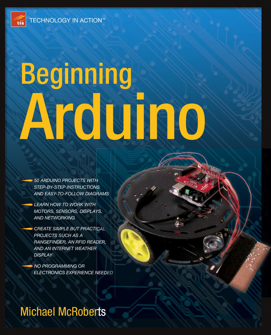
Beginning Arduino by Michael McRoberts

Author:Michael McRoberts
Language: eng
Format: mobi, epub, pdf
Publisher: Apress
Published: 2011-02-16T14:54:13.201109+00:00
Servo servo1; // Create a servo object
193
CHAPTER 9 ■ SERVOS
void setup()
{
servo1.attach(5); // Attaches the servo on Pin 5 to the servo object
}
void loop()
{
int angle = analogRead(0); // Read the pot value
angle=map(angle, 0, 1023, 0, 180); // Map the values from 0 to 180 degrees
servo1.write(angle); // Write the angle to the servo
delay(15); // Delay of 15ms to allow servo to reach position
}
Project 25 – Servo Control – Code Overview
First, the Servo.h library is included:
#include <Servo.h>
Then a Servo object called servo1 is declared:
Servo servo1; // Create a servo object
In the setup loop, you attach the servo you have just created to Pin 5:
servo1.attach(5); // Attaches the servo on Pin 5 to the servo object
The attach command attaches a created servo object to a designated pin. The attach command can
take either one parameter, as in your case, or three parameters. If three parameters are used, the first
parameter is the pin, the second is the minimum (0 degree) angle in pulse width in microseconds
(defaults to 544), and the third parameter is the maximum degree angle (180 degrees) in pulse width in
microseconds (defaults to 2400). This will be explained in the hardware overview. For most purposes you
can simply set the pin and ignore the optional second and third parameters.
You can connect up to 12 servos to an Arduino Duemilanove (or equivalent) and up to 48 on the
Arduino Mega—perfect for robotic control applications!
Note that using this library disables the analogWrite (PWM) function on Pins 9 and 10. On the Mega
you can have up to 12 motors without interfering with the PWM functions. The use of between 12 and 23
motors will disable the PWM functionality on Pins 11 and 12.
In the main loop, read the analog value from the potentiometer connected to Analog Pin 0:
int angle = analogRead(0); // Read the pot value
Then that value is mapped so the range is now between 0 and 180, which will correspond to the
degree angle of the servo arm:
angle=map(angle, 0, 1023, 0, 180); // Map the values from 0 to 180 degrees
Then you take your servo object and write the appropriate angle, in degrees, to it (the angle must be
between 0 and 180 degrees):
194
CHAPTER 9 ■ SERVOS
servo1.write(angle); // Write the angle to the servo
Finally, a delay of 15ms is programmed to allow the servo time to move into position:
delay(15); // Delay of 15ms to allow servo to reach position
You can also detach() a servo from a pin, which will disable it and allow the pin to be used for
something else. Also, you can read() the current angle from the servo (this is the last value passed to the
write() command).
You can read more about the Servo library on the Arduino website athttp://arduino.cc/
en/Reference/Servo.
Project 25 – Servo Control – Hardware Overview
A servo is a little box that contains a DC electric motor, a set of gears between the motor and an output
shaft, a position sensing mechanism, and the control circuit. The position sensing mechanism feeds
back the servo’s position to the control circuitry, which uses the motor to adjust the servo arm to the
position that the servo should be at.
Download
Beginning Arduino by Michael McRoberts.epub
Beginning Arduino by Michael McRoberts.pdf
This site does not store any files on its server. We only index and link to content provided by other sites. Please contact the content providers to delete copyright contents if any and email us, we'll remove relevant links or contents immediately.
| Coding Theory | Localization |
| Logic | Object-Oriented Design |
| Performance Optimization | Quality Control |
| Reengineering | Robohelp |
| Software Development | Software Reuse |
| Structured Design | Testing |
| Tools | UML |
Deep Learning with Python by François Chollet(11874)
Hello! Python by Anthony Briggs(9365)
OCA Java SE 8 Programmer I Certification Guide by Mala Gupta(9336)
The Mikado Method by Ola Ellnestam Daniel Brolund(9300)
Dependency Injection in .NET by Mark Seemann(8853)
Algorithms of the Intelligent Web by Haralambos Marmanis;Dmitry Babenko(7845)
Test-Driven iOS Development with Swift 4 by Dominik Hauser(7306)
Grails in Action by Glen Smith Peter Ledbrook(7291)
The Well-Grounded Java Developer by Benjamin J. Evans Martijn Verburg(7111)
Secrets of the JavaScript Ninja by John Resig Bear Bibeault(5951)
Kotlin in Action by Dmitry Jemerov(4633)
Practical Vim (for Kathryn Amaral) by Drew Neil(3724)
Cracking the GRE Premium Edition with 6 Practice Tests, 2015 (Graduate School Test Preparation) by Princeton Review(3590)
Linux Device Driver Development Cookbook by Rodolfo Giometti(3390)
Learn Windows PowerShell in a Month of Lunches by Don Jones(3236)
Learning Java by Patrick Niemeyer & Daniel Leuck(2867)
Learning React: Functional Web Development with React and Redux by Banks Alex & Porcello Eve(2831)
Becoming a Dynamics 365 Finance and Supply Chain Solution Architect by Brent Dawson(2582)
Mastering Java 9 by Dr. Edward Lavieri(2569)
